Functional Test: A Final Manufacturing Step
Functional test (FCT) is used as a final manufacturing step. It provides a pass/fail determination on finished PCBs before they are shipped. An FCT’s purpose in manufacturing is to validate that product hardware is free of defects that could, otherwise, adversely affect the product’s correct functioning in a system application.
In short, FCT verifies a PCB’s functionality and its behavior. It is important to emphasize that the requirements of a functional test, its development, and procedures vary widely from PCB to PCB and system to system.
Functional testers typically interface to the PCB under test via its edge connector or a test-probe point. This testing simulates the final electrical environment in which the PCB will be used.
The most common form of functional test, known as "hot mock-up" simply verifies that the PCB is functioning properly. More sophisticated functional tests involve cycling the PCB through an exhaustive range of operational tests.
Customer Advantages of Functional Test:
- Functional test simulates the operating environment for the product under test thereby minimizing the expensive cost for the customer to provide the actual testing equipment
- It eliminates the need for expensive system tests in some cases, which saves the OEM lots of time and financial resources.
- It can check the functionality of the product anywhere from 50% to 100% of the product being shipped thereby minimizing the time and effort on the OEM to check and debug it.
- Prudent testing engineers can extract the most productivity out of functional test thereby making it the most effective tool short of system test.
- Functional test enhances the other types of tests such as ICT and flying probe test, making the product more robust and error free.
A functional test emulates or simulates a product’s operational environment to check its correct functionality. The environment consists of any device that communicates with the device under test (DUT), for example, the DUT’s power supply or program loads necessary to make the DUT work properly.
The PCB is subjected to a sequence of signals and power supplies. Responses are monitored at specific points to ensure functionality is correct. The test is usually performed according to the OEM test engineer, who defines the specifications and test procedures. This test is best at detecting wrong component values, functional failures and parametric failures.
Test software, sometimes called firmware, allows production line operators to perform functional test in an automatic way through a computer. To do this, the software communicates with external programmable instruments as a digital multi-meter, I/O boards, communication ports. The software combined with the fixture interfacing the instruments with the DUT make it possible to perform a FCT.
Functional Test Example
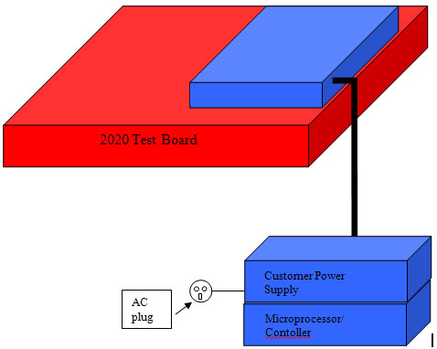
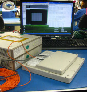
The PCB shown in Fig. 1 is part of a medical diagnostic imaging system. It is placed on a receiving test panel connected to the microprocessor based controller and power supply via a fiber optic cable and a 24V power connector, Fig. 1.

Figure 1: Block diagram of the overall system
The processor and power supply each consists of several PCBs and is regarded as systems. The fiber optic cable transfers data, and the 24V connector supplies power to the receiving test panel.
The board (DUT) is covered before testing. The processor is connected to the computer system via a serial cable and Ethernet connector. The power supply gets AC power and supplies 5V power to the CP via a power cable.
Firmware is developed based on testing requirements using a higher-level computer language like C, Perl, AutoITScript, or Java. The firmware sends commands from the computer to the controller and from there to the receiving test panel to check if certain specs on the board (DUT) are met or failed.

First, critical voltages need to be verified on the board (DUT) before putting it on the receptor test panel. Then communication software is used to check if proper booting up of the board occurs. This ensures that system is working and all the cables and wires are hookups are accurate.
For this particular board, the test development team produced a particular type of software to check the imaging of the overall system. Tests are performed to make sure that the image looks acceptable.
A board image can fail for various reasons. For example, those can be one or more bad critical voltages, defective component on a particular test channel, dysfunctional oscillation from crystal chip, among others. Thorough component level diagnostics must be done to determine the cause of the failure, which often can be a result of defective or wrong or disoriented IC, capacitor, voltage converter, filter, among others.
If a good dark image is found during test, further tests are performed on the board. Each different test is developed to find out how the board will actually perform with the overall imaging system in an actual real life application.
Rely On Savvy EMS Provider
Smart OEMs rely on a reputable EMS provider to include test as part of its product design and assembly. An EMS company adds considerable flexibility to an OEM’s technology storehouse. An experienced EMS provider designs and assembles a broad range of PCB products for an equally varied group of customers. Hence, it accumulates a much wider arsenal of knowledge, experience and expertise than their OEM customers.
OEM customers can benefit greatly by working with a knowledgeable EMS provider. The main reason is an experienced and savvy EMS provider draws from its experience base and makes valuable suggestions relating to different reliability techniques and standards. Consequently, an EMS provider is perhaps in the best position to help an OEM evaluate its test options and suggest the best test methods to improve product performance, manufacturability, quality, reliability, and most crucial, cost.

